Interrupts in Sim8085
Sim8085 now supports realistic hardware interrupt behavior, letting you write and test interrupt-driven programs just like on a real Intel 8085 system.
This includes:
- Line-based triggering (via UI toggles)
- Proper masking and enabling
- RST 7.5 latch behavior
- TRAP as a non-maskable interrupt
- SIM / RIM instruction support
🔢 Supported Interrupts
Section titled “🔢 Supported Interrupts”| Interrupt | Vector Address | Maskable? | Latching? | Notes |
|---|---|---|---|---|
| TRAP | 0x24 | ❌ No | ✅ Yes | Always enabled |
| RST 5.5 | 0x2C | ✅ Yes | ❌ No | Level-sensitive |
| RST 6.5 | 0x34 | ✅ Yes | ❌ No | Level-sensitive |
| RST 7.5 | 0x3C | ✅ Yes | ✅ Yes | Edge-triggered, latched |
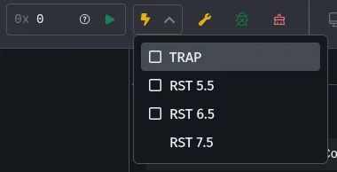
⚙️ Triggering Interrupts
Section titled “⚙️ Triggering Interrupts”Use the ⚡ Interrupt Panel from the top bar to toggle interrupt lines:
- Toggled on = line held HIGH
- Toggled off = line LOW
The CPU will respond to the line only if:
- Global interrupts are enabled (
EIexecuted) - The interrupt line is unmasked (via
SIM)
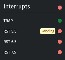
📊 Viewing Interrupt State
Section titled “📊 Viewing Interrupt State”The Interrupts sidebar panel shows:
- Whether global interrupts are enabled
- Which lines are enabled (i.e. not masked)
- Which interrupts are currently pending
Pending state means the line is HIGH and the interrupt is ready to fire as soon as it’s unmasked and enabled.
🧠 Special Behavior: RST 7.5
Section titled “🧠 Special Behavior: RST 7.5”RST 7.5 is:
- Edge-triggered (latched on rising edge)
- Latched internally even when disabled or masked
- Must be cleared manually via the
SIMinstruction (bit 4)
📥 SIM and RIM Instructions
Section titled “📥 SIM and RIM Instructions”Sim8085 supports:
SIM— set interrupt masks, reset RST 7.5 latch, control serial outputRIM— read interrupt masks, pending status, and serial input
Use these to programmatically enable/disable and inspect interrupt behavior.
✅ Tips for Writing Interrupt-Driven Programs
Section titled “✅ Tips for Writing Interrupt-Driven Programs”- Always use
EIbefore you expect interrupts - Don’t forget to
RETat the end of your ISR - Use
SIMto unmask or reset RST 7.5 latch if needed - You can hold lines high from the UI to simulate real hardware behavior
Example
Section titled “Example”EI ; Enable interruptsMVI A, 08H ; MSE = 1, mask bits = 000 → unmask allSIM
HLT ; Wait for interrupt
MVI A, 01H ; Resume after handling interruptHLT
ORG 002CH ; RST 5.5 ISRMVI B, 0AHRETNow toggle RST 5.5 from the ⚡ panel — the program will resume and execute the ISR.
💡 Example: Blink an LED Using RST 5.5
Section titled “💡 Example: Blink an LED Using RST 5.5”This program will blink an LED connected to port 1 five times when RST 5.5 is triggered. You can simulate the external interrupt by toggling the RST 5.5 line HIGH in the Interrupt Panel.
To test this progra,
- Enable
Simulate Instruction Timingin the Settings panel. - Keep the
LED Arraypanel open to observe the blinking lights. - Toggle RST 5.5 line HIGH in Interrupt Control Panel. Make it LOW to stop the lights from blinking.
ORG 0000HMVI A, 00HEILOOP:    INR A    MVI B, 0FFH    MVI C, 0FFH    CALL DELAY    JMP LOOP
; === Vector Table ===ORG 002CH  ; RST 5.5 vectorJMP RST_5_5_ISR
; === ISR Implementation ===ORG 0100HRST_5_5_ISR:    MVI D, 05H    CALL BLINK_LOOP    EI    RET
BLINK_LOOP:    MVI A, 01H    OUT 01H    CALL SHORT_DELAY
    MVI A, 00H    OUT 01H    CALL SHORT_DELAY
    DCR D    JNZ BLINK_LOOP    RET
SHORT_DELAY:    MVI B, 10H    MVI C, 00H    CALL DELAY    RET
DELAY:    DCX B    MOV A, B    ORA C    JNZ DELAY    RET